

In an era where high-speed communication and network systems require high speed, stability, and future readiness, fiber optic cables have become critical infrastructure in communication networks, ranging from buildings, factories, data centers, to nationwide telecommunication networks. This article will introduce you to techniques for fiber optic cable installation and testing, starting from the planning, installation, up to quality check of signals, to ensure your system is ready to function at full capacity and reduce future potential issues. Basic Understanding of Fiber Optic Cables Fiber optic cable testing aim to verify installation accuracy, find optical loss, and verify network performance, which will help reduce future issues such as unstable signals, drop in speed, or intermittent connections.
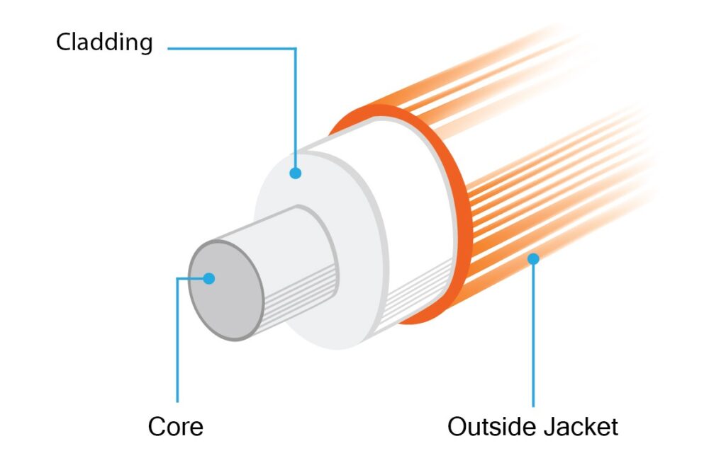
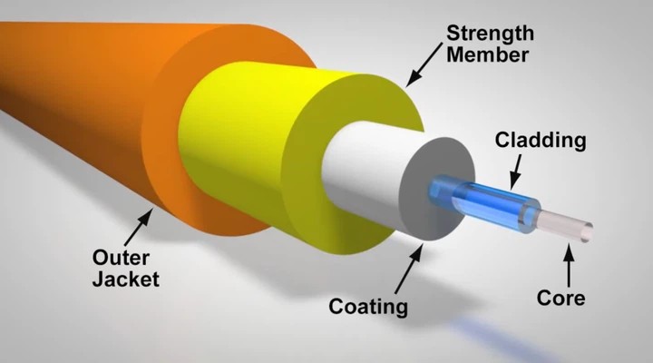
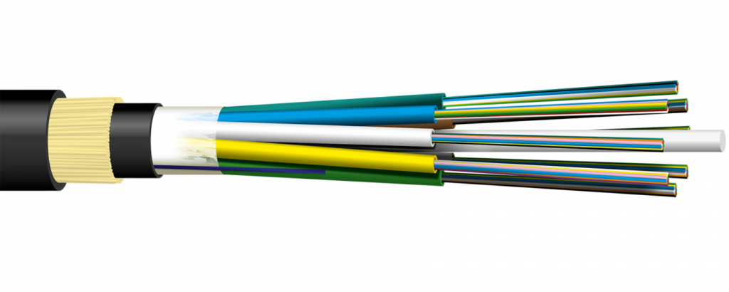
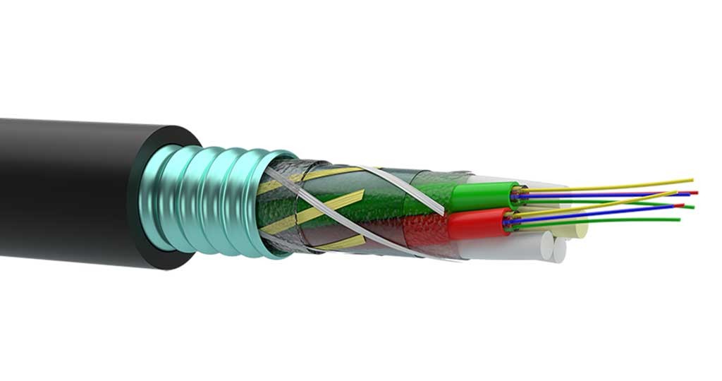
Main Structure of Fiber Optic Cables Generally, fiber optic cables consist of multiple layers, from the small glass core to the outer jacket that protects from physical damages, with each layer functioning as follows:
1.Core
A small component made of pure glass or plastic that functions as the main channel for transmitting light signals from the origin to the destination. The core size affects the type of fiber optic cables, which are divided into:
- Single-mode (SMF) with a small core (about 8-10 microns) for long-distance single-signal transmission, and
- Multimode (MMF) with a larger core (about 50-62.5 microns) for short-distance multi-mode signal transmission.

2. Cladding
This is the layer of material that surrounds the core of the fiber optic cable to control the total internal reflection of light. This ensures that the light signal travels completely within the core and does not leak out. This cladding layer has a special property in that it has a lower refractive index than the core, causing total internal reflection when light hits the boundary between the core and the cladding. Typically, it is about 125 µm thick (a standard for almost all cables).
3.Coating / Buffer
This is a critical component of the optical fiber that acts to protect the glass fiber from damage caused by external factors such as impact, abrasion from scratching, and moisture. Generally, the coating is applied onto the glass fiber immediately after the fiber drawing process to maintain its strength and reduce damage. It is a thin polymer layer (with an overall diameter of ~250 µm) and often comes in various colors to help identify the fiber (used in cables that bundle multiple cores, such as 12C, 24C, 48C, 96C, etc.).
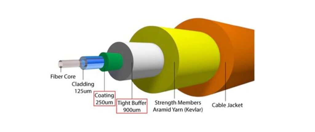
4. Strength Members
In fiber optic cables, these are components made from high-strength materials such as metal, fiberglass, or Kevlar. Their primary function is to absorb tensile force and protect the cable from damage. They help prevent pulling or crushing forces that could break the glass fibers during installation and usage. They are often made from Aramid Yarn (Kevlar) or other materials with high tensile strength, making the cable more flexible and durable.

5.Outer Jacket
This is the outermost layer of the cable, acting to protect the inner glass fibers from the external environment, such as pressure, abrasion, heat, moisture, UV light, and various factors like moisture, impact, scratches, and UV radiation. It is akin to the final armor that ensures the fiber optic cable’s durability and long lifespan. The final covering layer is made of PVC, LSZH (Low Smoke Zero Halogen), or PE. The color of the Jacket indicates the type of fiber.
Types of Optical Fiber Cables
Fiber optic cable (Optical Fiber Cable) is the heart of modern communication network systems. It can transmit signals over long distances, at high speeds, and is more resistant to interference than copper cables. However, when choosing to use them, it is necessary to understand that “there is not just one type of fiber optic cable,” but they are divided into different types based on their structure and primary uses, as follows:
1. Classification by Core Type The Core is the glass at the heart of the fiber optic cable, which can be primarily divided into two main types:
1.1 Single-Mode Fiber (SMF) Single-Mode Fiber (SMF) is a fiber optic cable designed for light to travel within a “single path” (Single Mode) inside a very small core. This prevents light from scattering or reflecting in multiple directions like Multimode fiber. Consequently, the signal is sharp and experiences very low loss, making it ideal for long-distance and high-speed communications.
Working Principle SMF utilizes a Laser Source to project light as a straight beam through the small core. This results in low signal attenuation (Attenuation) and reduces Dispersion (light scattering). Therefore, data can be transmitted over long distances while still maintaining excellent signal quality.
Commonly Used Wavelengths
- 1310 nm – Suitable for medium distances.
- 1550 nm – Suitable for very long distances and has the lowest loss.
Common Cable Standards
- OS1: Used indoors (Indoor).
- OS2: Used outdoors (Outdoor), supports greater distances.
Distance and Performance
- Supports distances ranging from several kilometers up to 100+ kilometers (depending on the equipment).
- Supports speeds of 10G, 40G, 100G and higher in modern communication systems.
Common Applications
- Backbone networks of organizations and Internet Service Providers (ISPs).
- Connecting between buildings (Campus Networks).
- Telecommunication systems and submarine cables.
- Long-distance Data Centers (Inter-Data Center).
Advantages
- Data can be sent very far without requiring frequent repeaters (Repeater).
- Effectively reduces signal loss and interference.
- Supports future high-speed technologies.
Considerations
- Equipment costs (e.g., SFP, Transceiver) are higher than Multimode.
- Installation and connection (Splicing/Connector) demand high precision.
- Requires specific test equipment, such as an Optical Loss Test Set or OTDR.
1.2 Multi-Mode Fiber (MMF) Multi-Mode Fiber (MMF) is a fiber optic cable with a larger core size, allowing light to travel via “multiple paths” (Multiple Modes) within a single fiber. Therefore, it is suitable for short to medium-distance applications, such as inside buildings or data centers.
Working Principle MMF uses LED or VCSEL light sources, which disperse light at various angles. When light travels multiple paths within the core, a phenomenon called Modal Dispersion occurs (light rays arrive at the destination at different times). This results in a limited operating distance compared to Single-Mode fiber.
Types of MMF According to Standards (OM Class)
- OM1 (62.5 µm): Legacy systems, supports low speeds.
- OM2 (50 µm): An improvement over OM1.
- OM3: Supports 10Gbps for a distance of ~300 meters.
- OM4: Supports 10–100Gbps for a distance longer than OM3.
- OM5: Supports SWDM (Shortwave WDM), increasing efficiency in Data Centers.
Distance and Performance (Approximate)
- 1Gbps: Maximum ~1 km.
- 10Gbps: ~300–550 meters.
- 40/100Gbps: ~100–150 meters (depending on OM3/OM4/OM5).
Common Applications
- LAN networks inside buildings.
- Data Centers and Server Rooms.
- Closed-Circuit Television (CCTV) systems.
- Industrial work requiring short-distance connections.
Advantages
- Lower cable and equipment (Transceiver) costs than Single-Mode.
- Easy installation, uses non-complex equipment.
- Suitable for systems requiring high speed over short distances.
Considerations
- Limited distance due to Modal Dispersion.
- If the distance increases, it might require auxiliary equipment or a switch to Single-Mode.
- The appropriate OM standard must be selected to match the required speed.
Recommended Tools for MMF Work To ensure accurate MMF installation and verification, specialized tools should be used, such as:
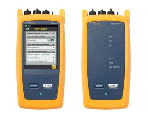
- CertiFiber™ Max Optical Loss Test Set Used for measuring the Optical Loss (Insertion Loss) of fiber optic cables. Suitable for Certification testing for both Multimode and Single-Mode fibers.
Benefits of using CertiFiber™ Max Optical Loss Test Set
- Accurately measures Optical Loss (Insertion Loss), helping to verify the quality of fiber optic cables.
- Used for system acceptance testing (Certification) to comply with standards such as TIA/ISO.
- Supports testing of both Single-Mode and Multi-Mode Fiber. Helps locate points with high signal loss, such as connectors or splice points.
- Reduces testing time with an Auto Test system and instant Pass/Fail results display.
- Increases confidence in handing over work to customers with reliable test results.
- Suitable for new installations, system upgrades, or network maintenance.
- Supports data recording and professional test report generation.
- Helps in rapid analysis and troubleshooting of fiber network issues.
- Increases efficiency and reduces errors in the work of technical teams.
2.OTDR (Optical Time Domain Reflectometer) Used to inspect distances, breaks, or loss points in cables, suitable for troubleshooting.
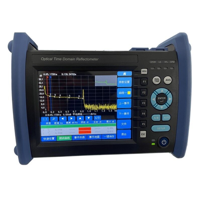
Benefits of using an OTDR (Optical Time Domain Reflectometer)
- Accurately measure the distance of the fiber optic cable throughout its entire length. Quickly locate cable breaks or fault points.
- Clearly identify positions where signal loss (Loss Events) occurs. Analyze the quality of splice points and connectors.
- Used for targeted troubleshooting and fixing fiber network issues. Display a Trace graph to provide an overview of the condition of the entire cable.
- Supports inspecting long-distance cables spanning many kilometers.
- Helps reduce the time to find problems when network system issues arise.
- Used for inspection before and after installation to verify work quality.
- Supports data recording and report generation for engineering work.
3.Visual Fault Locator (VFL) Used to detect breaks or light leaks in fiber optic cables at close range.

Benefits of using an Visual Fault Locator (VFL)
- Quickly detects fiber breaks.
- Clearly reveals light leakage locations using a red laser.
- Performs continuity checks to verify correct cable connections.
- Helps identify connector issues, such as loose, dirty, or damaged connections.
- Ideal for short-range troubleshooting, such as within buildings or data centers.
- Easy to use and uncomplicated, suitable for technicians of all levels.
- Reduces inspection and troubleshooting time.
- Suitable for inspecting patch cords and MPO/MTP cables.
- Used in conjunction with other tools like OTDR or Optical Loss Test Sets to
- mprove accuracy.
- Highly portable, perfect for field work and general installation tasks.
2. Classification by Application of Fiber Optic Cables
In addition to division by core type, fiber optic cables are designed with “external structures” suitable for different environments and installation characteristics to increase durability, safety, and lifespan. They can be divided as follows:
2.1 Indoor Fiber Optic Cable This type of cable is designed primarily for indoor use, emphasizing safety and installation flexibility.
Distinctive Features
- Uses LSZH (Low Smoke Zero Halogen) material, which reduces smoke and toxic gases in the event of a fire.
- Small size, lightweight, and easy to bend.
- Lacks water protection or heavy impact resistance comparable to outdoor cables.
Example Structures
- Tight-Buffered
- Simplex / Duplex
Suitable for
- Server racks, data centers, and server rooms.
- Indoor cable routing within offices and factories.
2.2 Outdoor Fiber Optic Cable Designed for use in external environments where it must withstand sunlight, rain, moisture, and temperature fluctuations.
Distinctive Features
- Features multiple protective layers, such as:
- Water Blocking Gel / Tape to prevent water ingress.
- Strength Member (FRP / Steel) to increase strength.
- Good resistance to UV and weather conditions.
- Stronger structure than indoor cables.
Suitable for
- Cable routing between buildings (Campus Network).
- External conduit installation.
- Ground burial (Direct Buried / Duct).
2.3 Aerial Fiber Optic Cable Used for overhead installation along utility poles or telecommunication towers.
Distinctive Features
- Contains a Messenger Wire (steel lashing) or a tension-bearing structure.
- Supports high tensile strength.
- Designed to withstand wind force and vibration.
Suitable for
- Long-distance cabling along utility poles.
- ISP or telecommunication network projects.
2.4 Armored Fiber Optic Cable
Cables with an added special protective layer to handle compressive forces and rodent attacks.
Distinctive Features
- Contains a layer of steel or metal (Steel Tape / Aluminum Armor).
- Prevents rats or other animals from biting the cable.
- High resistance to pressure and impact.
Suitable for
- Direct underground burial.
- Risk areas such as factories and construction sites.
2.5 Ribbon Fiber Optic Cable
Designed to support applications requiring a “high number of fiber strands” within a single cable.

Distinctive Features
- Arranges fiber strands in a flat configuration (Ribbon).
- Supports Mass Fusion Splicing (connecting multiple strands simultaneously).
- Reduces installation and maintenance time.
Suitable for
- Large-scale telecommunication networks.
- Hyperscale Data Centers.
- Projects requiring high fiber counts.
Planning Steps Before Fiber Optic Cable Installation
Good planning is the starting point of a high-quality fiber system, helping to reduce on-site problems, cut redundant costs, and ensure smooth installation. Key details are as follows:
1. Site Survey This step involves “collecting actual data” before starting installation to understand limitations and select the most appropriate approach.
What to do
- Measure the actual cabling distance
- To calculate cable length, allow for slack, and estimate the budget.
- Inspect the cabling route
- Are there sharp bends? (Must be careful with Bending Radius)
- Are there obstructions such as pipes, electrical systems, or building structures?
- Does it pass through risky areas like heat, water, or chemicals?
- Evaluate the environment
- To choose the right cable type, such as Indoor / Outdoor / Armored.
- Plan the best route
- Choose a route that is:
- Safe for the cable
- Minimizes bends
- Easily accessible in the future (Maintenance-friendly)
- Choose a route that is:
Tip: A drawing or layout diagram should be created to serve as a work plan and for later reference.
2. Equipment Selection Selecting the correct equipment will ensure system stability and support long-term usage.
Fiber Optic Cable Selection
- Single-Mode (SMF): Suitable for long distances, high speed.
- Multi-Mode (MMF): Suitable for short distances, such as indoors / Data Centers.
Main Equipment to Prepare
- ODF (Optical Distribution Frame)
- Used to organize and terminate fiber cables in a Rack cabinet.
- Patch Panel
- A connection point for managing cables and network equipment.
- Connector / Adapter
- Such as LC, SC, ST; must select to match the end-point equipment.
- Patch Cord / Pigtail Cables
- Used for connecting between equipment.
- Cable Protection Equipment
- Duct / Conduit: Protects cables from impact.
- Cable Tray: For organizing cables within a building.
Fiber Optic Cable Installation Techniques
Installing fiber optic cables with high quality is not just about making them “work,” but it involves considering long-term stability and future maintenance. Each step contains key details as follows:

1. Cable Installation
This step directly impacts signal quality. Improper installation can lead to signal loss or even permanent cable damage.
Details:
Bending Radius Control
- The bending radius should generally not be less than 10 times the cable diameter (in some cases, 15–20 times is recommended).
- Excessive bending can cause light leakage, known as Macro-bending Loss.
Tensile Strength Control
- Do not exceed the manufacturer’s specified pulling force (e.g., 600N).
- Excessive tension may damage or deform the internal fiber.
Cable Routing Through Ducts/Trays
- Use the “Pull & Feed” technique to distribute force evenly.
- Apply cable lubricant for long-distance installations.
- Avoid twisting or friction against sharp edges.
Route Planning
- Keep the path as straight as possible.
- Minimize bends and avoid high-risk areas.

2. Fiber Splicing
Splicing is the point where signal loss is most likely to occur, so it must be performed with high precision and care.
Details:
Use a Fusion Splicer
- This is the best method, providing very low loss (approximately 0.02–0.1 dB).
Fiber Preparation Before Splicing
- Strip the fiber carefully
- Clean with 99% isopropyl alcohol (IPA)
- Use a cleaver to cut the fiber end with a precise 90° angle and a smooth surface
Post-Splicing Inspection
- Check the loss value displayed on the splicer
- Verify again using OTDR or a loss measurement device
Splice Protection
- Use a heat shrink sleeve to protect the splice:
- Prevent moisture ingress
- Reduce mechanical stress (bending/pressure)
- Increase the durability of the splice point
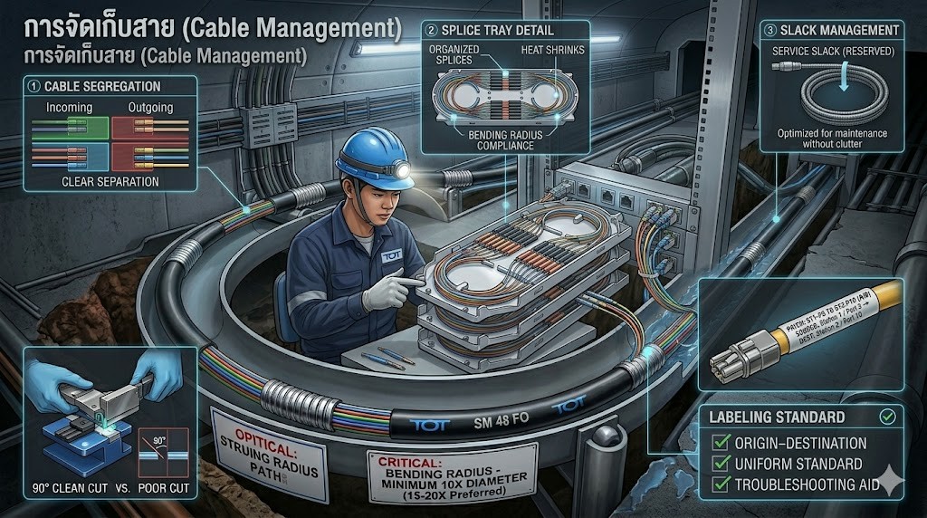
3. Cable Management
Proper cable organization helps maintain a professional system appearance and makes future maintenance much easier.
Details:
Organized Storage in ODF / Patch Panel
- Clearly separate incoming and outgoing cables
- Use splice trays to manage and protect splice points
Avoid Over-Tight Coiling
- Do not coil cables too tightly
- Always maintain the proper bending radius, even in storage areas
Slack Management
- Leave sufficient slack for future maintenance or repairs
- Avoid excessive slack that can cause clutter
Clear Labeling
- Identify both source and destination of each cable
- Use consistent labeling standards across the entire system
- Helps significantly reduce troubleshooting time
Fiber Optic Testing Techniques
After fiber optic installation is completed, testing is the final step to ensure the system is fully operational, meets required standards, and is free from hidden issues. Each testing tool serves a different purpose, as outlined below:
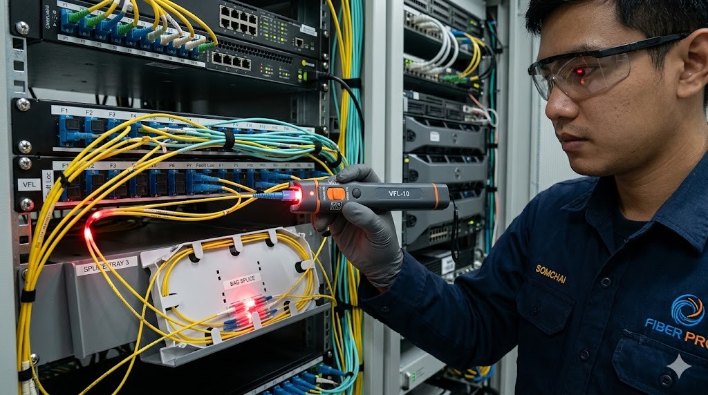
1. Visual Fault Locator (VFL)
Working Principle
Emits a visible red laser light into the fiber to identify points where light leaks out.
Details:
- Instantly detects fiber breaks or disconnected cables
- Visible light leakage helps identify:
- Excessive bending (Macro-bending)
- Loose or damaged connectors
- Faulty splice points
- Suitable for short-distance testing (approximately 5–10 km or less, depending on the model)
Advantages:
- Easy to use
- Immediate visual results
Limitations:
- Cannot measure optical loss in numerical values
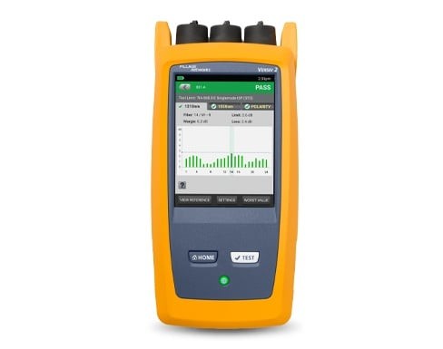
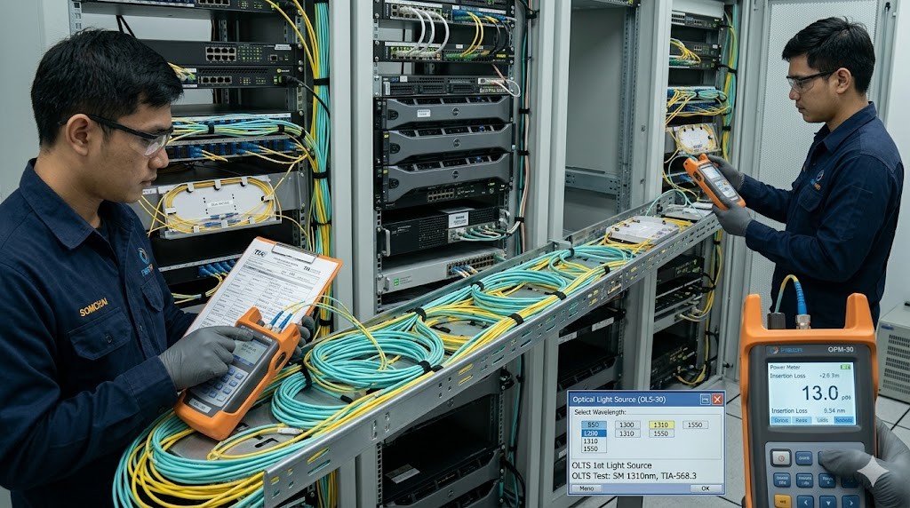
2. Optical Power Meter & Light Source (OLTS)
Working Principle
A light source transmits optical signals from one end of the fiber, while a power meter measures the received power at the other end to calculate Optical Loss (dB).
Details:
- Measures end-to-end insertion loss of the fiber link
- Supports multiple wavelengths, such as:
- 850, 1300 nm (Multimode)
- 1310, 1550 nm (Single-mode)
- Used for certification testing in accordance with TIA/ISO standards
Result Interpretation:
- Compare measured values with the loss budget
- Typical values:
- Splice: ~0.1–0.3 dB
- Connector: ~0.2–0.5 dB
Advantages:
- Provides accurate and reliable measurements
- Ideal for validating installation quality
Limitations:
- Cannot identify the exact location of faults
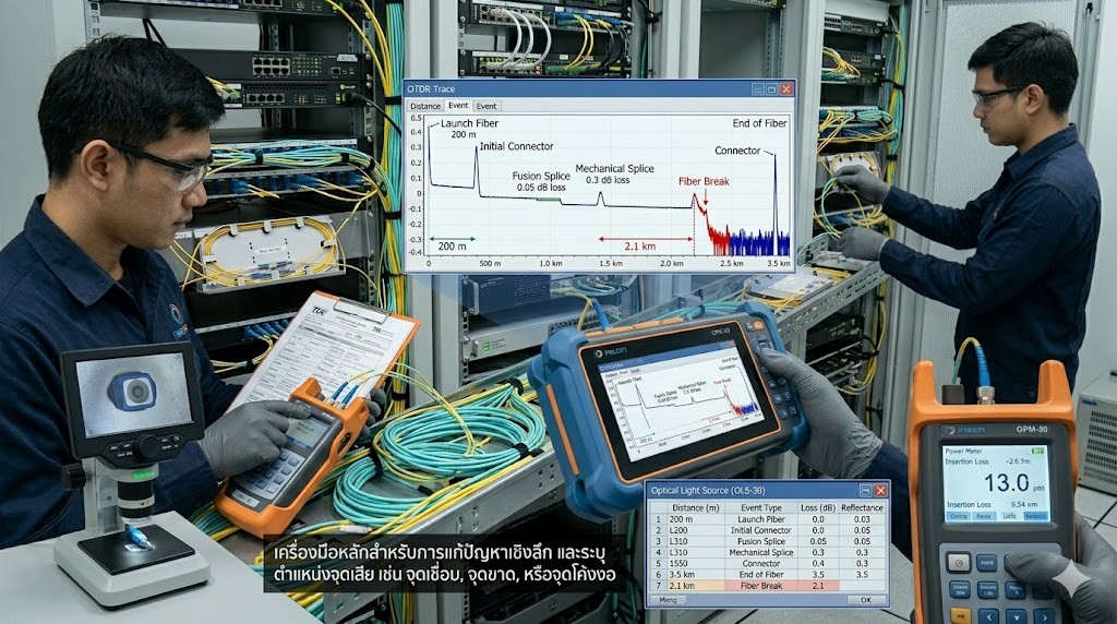
3. OTDR (Optical Time Domain Reflectometer)
Working Principle
Sends light pulses into the fiber and analyzes the backscattered signals to generate a graphical trace of the entire fiber link.
Details:
- Identifies locations of:
- Splice points
- Loss events
- Fiber breaks
- Displays distance in meters along with the loss value at each point
- Capable of testing long-distance fiber links over several kilometers
Applications:
- Ideal for advanced troubleshooting
- Widely used in large-scale networks such as ISP and backbone infrastructure
- Used to create a baseline record for future comparison and maintenance
Advantages:
- Provides a full overview of the fiber link
- Accurately pinpoints fault locations
Limitations:
- Requires technical knowledge to interpret trace graphs
Installation and Testing Standards You Should Know
To ensure proper installation and testing, it is important to follow international standards such as:
| Standard | Description |
| TIA/EIA-568 | Telecommunications cabling standards for commercial buildings |
| ISO/IEC 11801 | Generic cabling standard for structured network infrastructure |
| IEC 61280 | Fiber optic testing standards |
| IEEE 802.3 | Ethernet standards over fiber optic networks |
Post-Installation Maintenance
To ensure long-term performance and minimize future issues, regular maintenance of fiber optic cables is essential:
- Clean connectors using a fiber cleaning cloth or alcohol swab before every use
- Perform periodic inspections, especially in areas exposed to pressure, tension, or near machinery
- Keep test reports for every link as records for future reference and troubleshooting
Summary
Efficient fiber optic installation and testing do not rely solely on selecting the right cable. They require a clear understanding of fiber types, proper installation techniques, and the use of appropriate testing tools working together.
During installation, it is important to choose the right type of cable based on the environment—whether indoor, outdoor, or high-risk areas. Attention should also be given to bending radius, connector cleanliness, and proper cable management to minimize signal loss.
For testing, using specialized tools such as:
- Optical Loss Test Set for certification
- OTDR for in-depth analysis
- VFL for basic inspection
helps ensure accurate, fast, and reliable verification of fiber performance.
The key principle is simple: “Install correctly + Test thoroughly”