


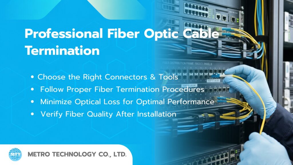
In Fiber Optic network installation, the quality of fiber optic cable termination is a critical factor that directly affects overall system performance. Improper termination can result in high Optical Loss, unstable connections, or even cause the system to fail acceptance testing according to industry standards.
Although Fusion Splicing technology is widely used today, fiber optic cable termination remains an essential skill that network installation technicians and system engineers must thoroughly understand.
This article will introduce the professional process of fiber optic cable termination, from equipment preparation, cable stripping, and fiber cleaving, to post-installation quality inspection.
Understanding Fiber Optic Cable Structure Before Termination
Before starting the fiber optic cable termination process, installation technicians should first understand the structure of a fiber optic cable. Each layer of the cable serves a different purpose and directly affects the quality of signal transmission within the system.
Although fiber optic cables may appear similar to conventional communication cables externally, internally they consist of a complex and precisely engineered structure designed to transmit data using light over long distances at high speeds.
In general, a fiber optic cable consists of the following key components:
1. Core (Light-Guiding Core)
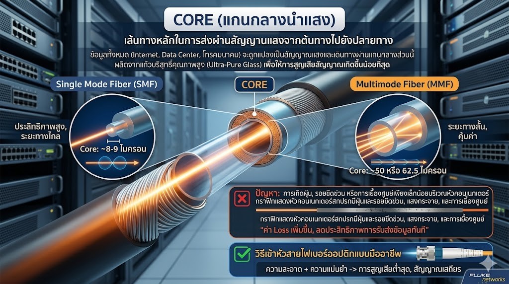
The Core is the most important part of a fiber optic cable. It serves as the primary pathway for transmitting light signals from the source to the destination.
All data transmitted through the network system—whether internet traffic, Data Center information, or telecommunications signals—is converted into light signals and travels through this central core.
The Core is manufactured from ultra-pure glass to minimize signal loss as much as possible. Core size varies depending on the type of fiber optic cable, such as:
- Single Mode Fiber: Core diameter approximately 8–9 microns
- Multimode Fiber: Core diameter approximately 50 or 62.5 microns
Because the Core is extremely small, even minor dust particles, scratches, or slight misalignment at the connector interface can significantly increase Loss values and immediately reduce data transmission performance.
2. Cladding (Glass Cladding Layer)
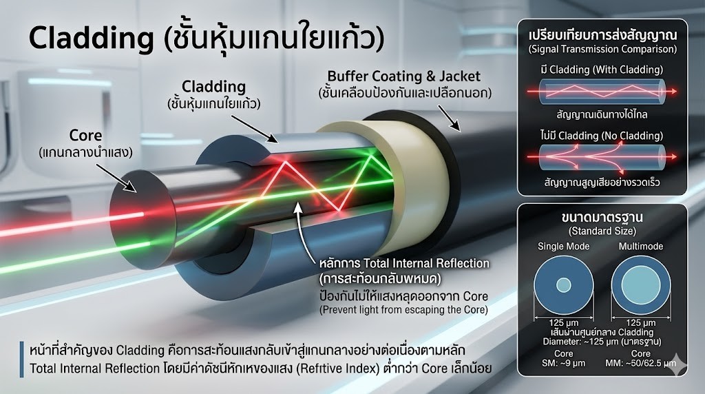
The Cladding is the glass layer surrounding the Core and has a slightly lower Refractive Index than the Core.
The primary function of the Cladding is to continuously reflect light back into the Core through the principle of Total Internal Reflection.
Simply put, the Cladding prevents light from escaping the Core while traveling through the fiber optic cable.
Without Cladding, light signals would rapidly dissipate from the cable, making long-distance data transmission impossible.
Typically, the Cladding has a standard diameter of approximately 125 microns for both Single Mode and Multimode fibers.
Although the Cladding does not directly carry information, it plays a crucial role in the signal transmission efficiency of the system.
3. Coating (Protective Coating Layer)
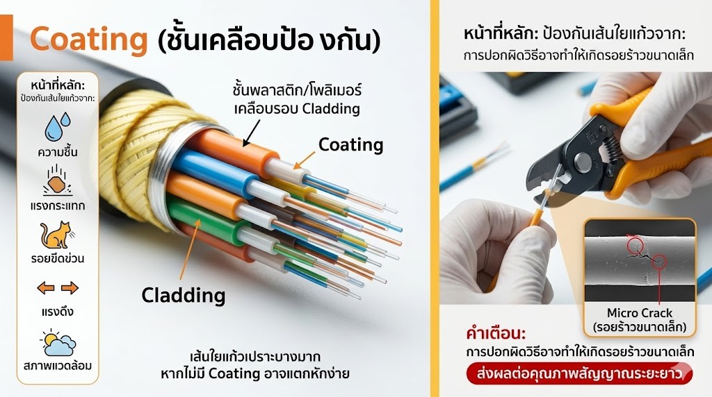
The Coating is a plastic or polymer layer applied around the Cladding. Its primary purpose is to protect the glass fiber from:
- Moisture
- Impact
- Scratches
- Tensile stress
- Environmental damage
The glass fiber inside is extremely fragile. Without the protection provided by the Coating, it could easily break even under minimal pressure.
During the fiber optic cable termination process, technicians must strip part of the Coating to prepare the glass fiber for splicing or connector installation.
This step must be performed carefully because improper stripping can create small cracks (Micro Cracks) in the fiber, which may affect signal quality over the long term.
4. Strength Member (Reinforcement Layer)
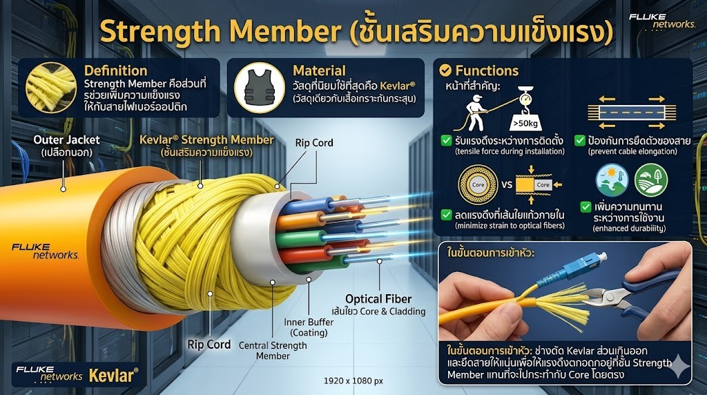
The Strength Member is the component that provides additional mechanical strength to the fiber optic cable. The most commonly used material is Kevlar, the same material used in bulletproof vests.
The functions of the Strength Member include:
- Withstanding pulling forces during installation
- Preventing cable elongation
- Reducing the likelihood of tensile forces reaching the internal glass fiber
- Increasing durability during operation
When installing fiber optic cables indoors or outdoors, installation tension can reach several tens of kilograms. Without a Strength Member, the internal glass fiber could be damaged or broken immediately.
During the termination process, technicians typically trim excess Kevlar and secure the cable properly so that tensile forces are absorbed by the Strength Member rather than being applied directly to the Core.
5. Outer Jacket (Outer Protective Jacket)
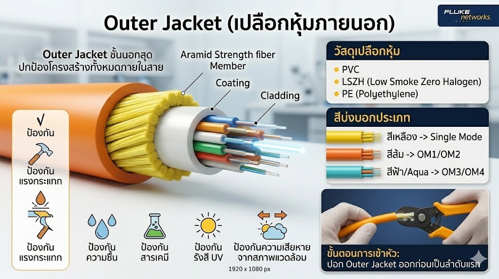
The Outer Jacket is the outermost layer of a fiber optic cable and serves to protect the entire internal cable structure. The material used for the outer jacket may vary depending on the application, such as:
- PVC
- LSZH (Low Smoke Zero Halogen)
- PE (Polyethylene)
The primary functions of the Outer Jacket include:
- Protection against impact
- Protection against moisture
- Protection against chemicals
- Protection against UV radiation
- Protection against environmental damage
The color of the Jacket can also indicate the type of fiber optic cable, for example:
- Yellow for Single Mode fiber
- Orange for Multimode OM1/OM2 fiber
- Blue or Aqua for Multimode OM3/OM4 fiber
During the cable termination process, technicians must first strip off the Outer Jacket to gain access to the internal cable structure.
Why Does Fiber Optic Cable Termination Require High Precision?
When comparing the size of the Core to a human hair, the difference becomes obvious:
- Single Mode Fiber Core: approximately 9 microns
- Multimode Fiber Core: approximately 50–62.5 microns
- Human hair: approximately 70–100 microns
This means that a single dust particle, barely visible to the naked eye, may actually be larger than the Core of a fiber optic cable.
For this reason, every step of fiber optic cable termination—including cable stripping, cleaning, fiber cleaving, and connector assembly—must be performed with precision, cleanliness, and in accordance with industry standards. This ensures the lowest possible Optical Loss and enables the network system to operate at maximum efficiency over the long term.
Equipment Required for Fiber Optic Cable Termination
Achieving a standard-compliant fiber optic cable termination does not depend solely on the technician’s skills. The tools and equipment used also play a significant role in determining the quality of the installation. Since fiber optic cables transmit signals at the micron level, even minor mistakes can result in high Loss values, unstable signals, or reduced system performance over the long term.
Therefore, before starting any installation work, it is important to prepare the necessary tools and select high-quality equipment to ensure accurate cable termination and the best possible results.
1. Fiber Stripper
A Fiber Stripper is a tool used to remove the protective Coating layer surrounding the glass fiber Core, preparing the fiber for termination or splicing.
Because the glass fiber Core is extremely fragile, using pliers or general-purpose tools for stripping may cause scratches or cracks on the fiber. Such damage is often invisible to the naked eye but can significantly increase Loss values later.
A Fiber Stripper is specifically designed with grooves sized to match the coating layers of fiber optic cables, allowing the Coating to be removed accurately without damaging the glass fiber inside.
Benefits of a Fiber Stripper
- Fast and consistent cable stripping
- Reduced risk of damage to the glass fiber Core
- Lower chance of scratches on the fiber
- Improved connection quality
2. Kevlar Scissors
Most fiber optic cables contain Kevlar fibers that serve as the Strength Member, providing mechanical reinforcement and absorbing tensile forces during installation.
Kevlar is extremely tough. Using ordinary scissors to cut it is often difficult, resulting in untidy cable ends and potential damage to cutting tools.
Kevlar Scissors are specifically designed to cut Kevlar fibers cleanly and efficiently.
Benefits of Kevlar Scissors
- Easy cutting of Kevlar fibers
- Reduced tensile stress that could affect the glass fiber Core
- Cleaner and more organized cable preparation
- Faster termination process
3. Fiber Cleaver
The Fiber Cleaver is one of the most important tools used in fiber optic cable termination.
Its function is to cut the end of the glass fiber as flat and perpendicular as possible. Typically, a cleave angle close to 90 degrees is required.
If the fiber end is uneven or angled, it may cause:
- Increased Optical Loss
- Higher Back Reflection
- Poor connection quality
- Incomplete Fusion Splicing
A high-quality Fiber Cleaver can achieve micron-level cutting accuracy, directly affecting the quality of the installation.
Benefits of a Fiber Cleaver
- Produces smooth and uniform fiber ends
- Reduces signal loss
- Improves connection quality
- Makes it easier to meet testing standards
4. Fiber Connector
A Fiber Connector is the connector used to connect fiber optic cables to network devices or communication equipment.
There are several types of fiber connectors, including:
- SC
- LC
- FC
- ST
- MPO/MTP
The connector type must be selected according to the equipment and system requirements.
It must also match the type of fiber optic cable being used, such as:
- Single Mode
- Multimode
Using the wrong connector type may result in high Loss values or compatibility issues.
Benefits of High-Quality Fiber Connectors
- Reduced signal loss
- Improved system stability
- Reliable long-term connectivity
- Reduced maintenance issues in the future
5. 99% Alcohol
99% purity alcohol is used to clean glass fibers and connector end faces before making a connection.
During installation, various contaminants may be present, such as:
- Dust
- Fingerprint oil residue
- Moisture
- Debris from cable cutting
These contaminants are among the primary causes of high Loss values and unstable connections.
Using 99% Alcohol effectively removes contaminants without leaving residue behind.
Benefits of 99% Alcohol
- Reduces contamination on fiber surfaces
- Lowers Loss values
- Improves connection quality
- Reduces the risk of Back Reflection
6. Lint-Free Wipe
Even when alcohol is used for cleaning, using ordinary cloths may leave fabric fibers on the glass fiber surface.
A Lint-Free Wipe is a specialized cleaning cloth designed not to leave fibers or dust after use.
For this reason, it is a standard accessory used together with 99% Alcohol in Fiber Optic applications.
Benefits of Lint-Free Wipes
- Leaves no dust or fibers behind
- Improves cleaning effectiveness
- Reduces contamination on connector end faces
- Increases testing accuracy
7. Visual Fault Locator (VFL)
A VFL is a device that injects a red laser light into a fiber optic cable to verify cable continuity and identify fault locations.
As the light travels through the fiber, if there is a:
- Broken cable
- Cracked fiber
- Bent fiber
- Damaged connection point
the red light will immediately leak out at that location.
Benefits of a VFL
- Quickly verifies continuity
- Locates cable faults
- Checks polarity
- Reduces troubleshooting time
8. Fiber Inspection Microscope
A Fiber Inspection Microscope is used to examine the condition of connector end faces under high magnification.
It can reveal:
- Dust particles
- Oil contamination
- Scratches
- Cracks
- Ferrule damage
Fiber optic professionals worldwide recognize that most fiber system issues originate from contaminated connector end faces.
Therefore, inspection before connection is considered a critical step according to the principle:
Inspect Before You Connect
Benefits of a Fiber Inspection Microscope
- Reduces problems caused by high Loss values
- Increases system reliability
- Reduces troubleshooting time
- Improves acceptance testing accuracy
9. Optical Power Meter
An Optical Power Meter is used to measure the optical power received at the end of a fiber optic cable.
The measured value helps determine whether:
- The system is transmitting signals properly
- The optical power level is sufficient
- The transmitting equipment is functioning correctly
It is a fundamental tool required for the installation and maintenance of all types of fiber optic systems.
Benefits of an Optical Power Meter
- Accurate optical power measurement
- Verification of system performance
- Useful for network troubleshooting
- Confirms installation quality
10. Optical Light Source
An Optical Light Source works together with an Optical Power Meter by transmitting a standardized light signal into the fiber optic cable.
When the receiving end uses a Power Meter to measure the received signal, the Optical Loss of the link can be calculated.
Loss measurement is one of the most important standards used for Fiber Optic system acceptance testing.
Benefits of an Optical Light Source
- Measures fiber optic cable Loss
- Verifies installation quality
- Used together with a Power Meter for Fiber Certification
- Confirms that the system complies with required standards
The Importance of Choosing High-Quality Equipment
No matter how experienced a technician may be, using substandard equipment can prevent the installation from achieving the desired results.
High-quality tools help to:
- Reduce Optical Loss
- Improve installation accuracy
- Minimize Human Error
- Reduce fieldwork time
- Extend system lifespan
- Make compliance with acceptance testing standards easier
Therefore, preparing suitable and high-quality equipment is a crucial first step in professional fiber optic cable termination and a key factor that directly impacts long-term network system performance.
Professional Fiber Optic Cable Termination Procedure
Step 1: Cut the Fiber Optic Cable and Prepare the Required Cable Length
Begin by determining the required cable length for the installation.
Always allow extra cable length for cable management inside a Rack cabinet or Patch Panel. This makes future maintenance, equipment relocation, or system upgrades more convenient.
After cutting the cable, inspect its external condition for any signs of crushing, kinks, bends, or other physical damage.
Step 2: Strip the Outer Jacket
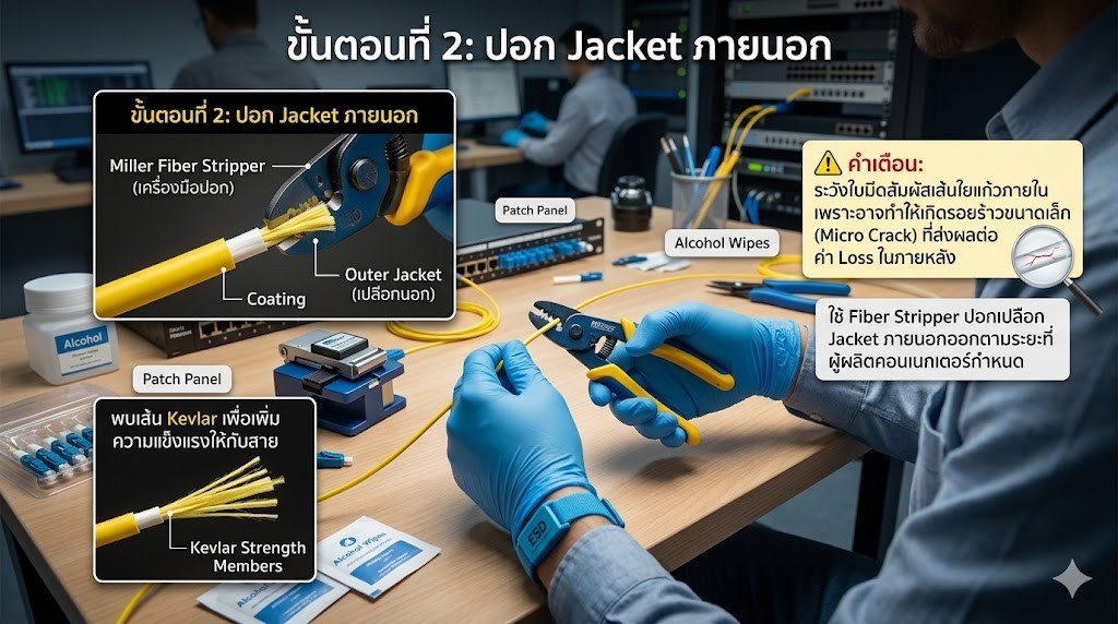
Use a Fiber Stripper to remove the outer Jacket according to the stripping length specified by the connector manufacturer.
During the stripping process, care must be taken to ensure that the blade does not come into contact with the internal glass fiber, as this may create microscopic cracks that can increase Loss values later.
Once the Jacket has been removed, the Kevlar fibers that provide mechanical strength to the cable will be exposed.
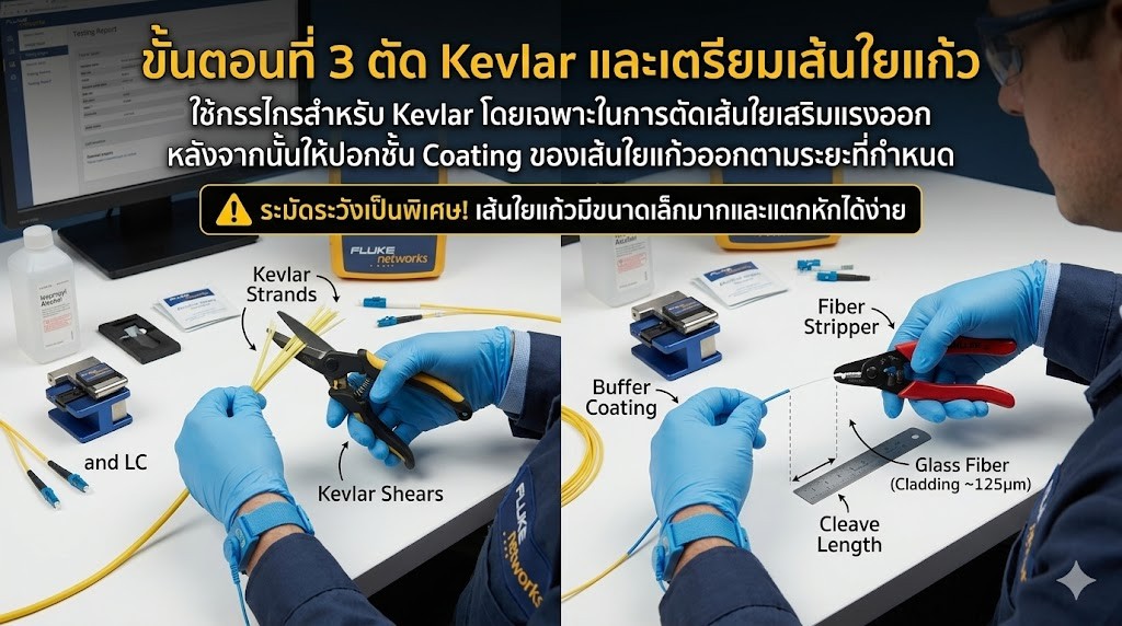
Step 3: Cut the Kevlar and Prepare the Glass Fiber
Use dedicated Kevlar Scissors to trim the reinforcing Kevlar fibers.
Afterward, strip the Coating layer from the glass fiber according to the specified length requirements.
This step must be performed with extreme care, as the glass fiber is extremely small and can be easily damaged or broken.
Step 4: Clean the Glass Fiber
Use a Lint-Free Wipe moistened with high-purity Isopropyl Alcohol to clean the glass fiber, wiping from the inside outward.
Do not wipe back and forth, as this may redeposit contaminants onto the fiber surface.
A clean fiber helps ensure higher-quality cleaving and better connection performance.

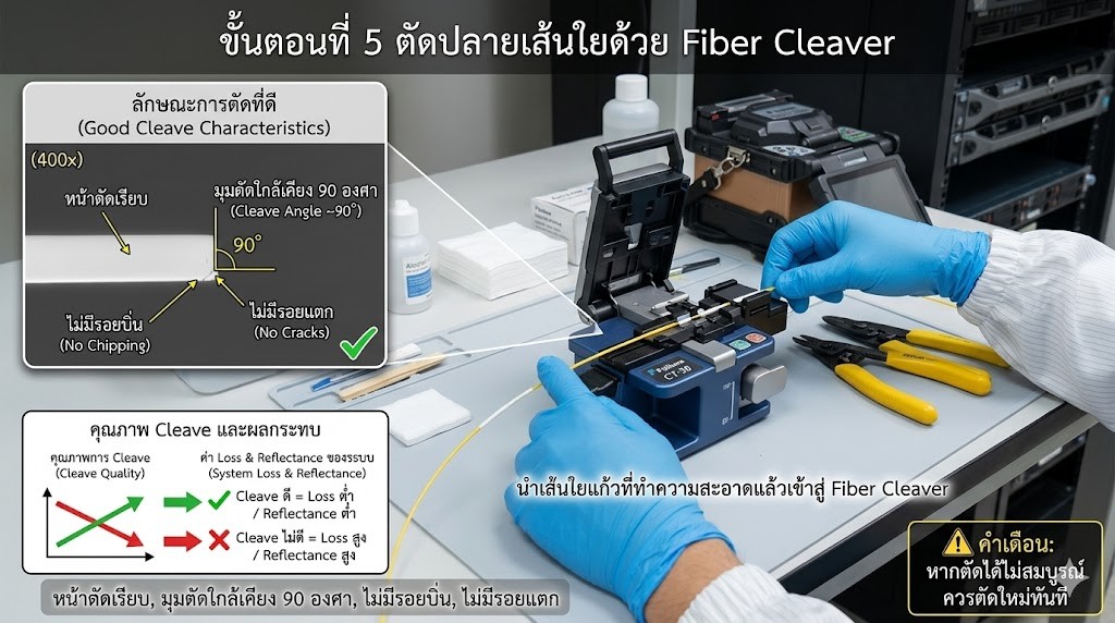
Step 5: Cleave the Fiber End Using a Fiber Cleaver
Place the cleaned glass fiber into the Fiber Cleaver.
A proper cleave should have the following characteristics:
- Smooth end face
- Cleave angle close to 90 degrees
- No chips
- No cracks
The quality of the cleave directly affects the Loss and Reflectance values of the system.
If the cleave is not satisfactory, the fiber should be re-cleaved immediately.
Step 6: Install the Fiber Connector
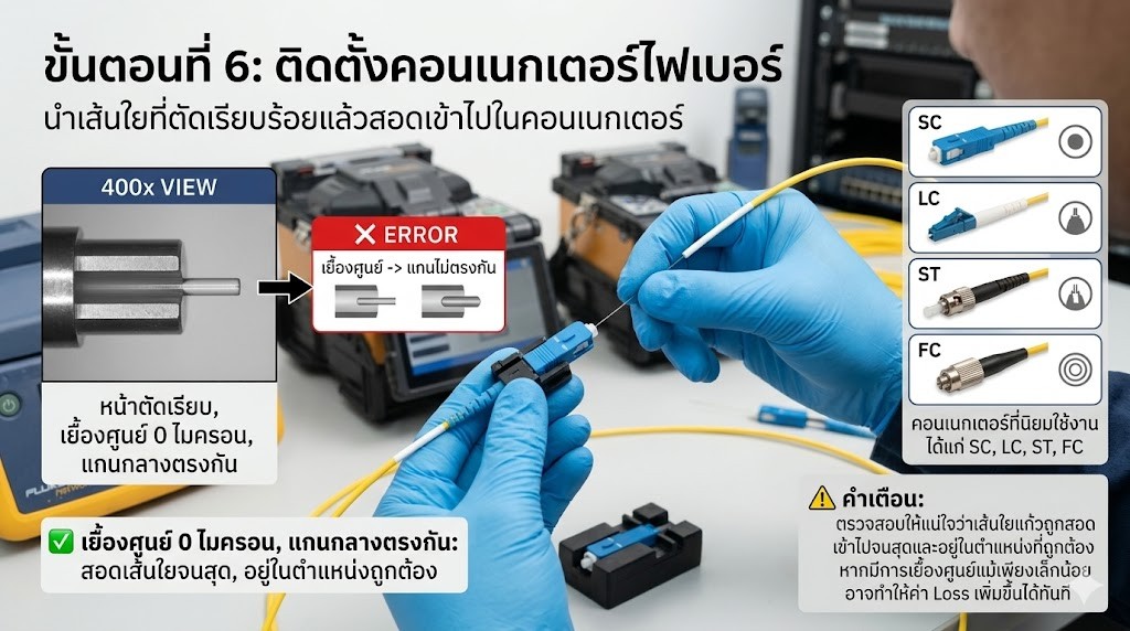
Insert the properly cleaved fiber into the connector.
Commonly used connector types include:
- SC
- LC
- ST
- FC
During this step, ensure that the glass fiber is fully inserted and correctly positioned inside the connector.
Even slight misalignment can immediately increase Loss values.
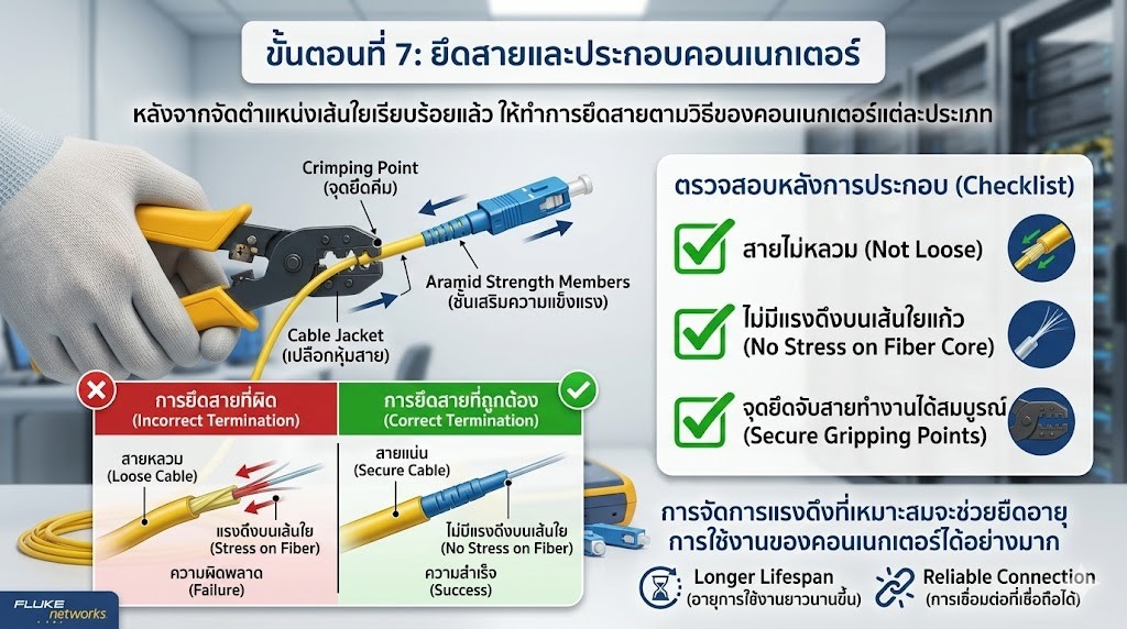
Step 7: Secure the Cable and Assemble the Connector
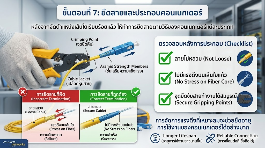
After the fiber has been properly aligned, secure the cable according to the installation method specified for the connector type being used.
Verify that:
- The cable is firmly secured
- No tensile force is applied to the glass fiber
- The cable retention mechanism is functioning properly
Proper strain relief management can significantly extend the service life of the connector.
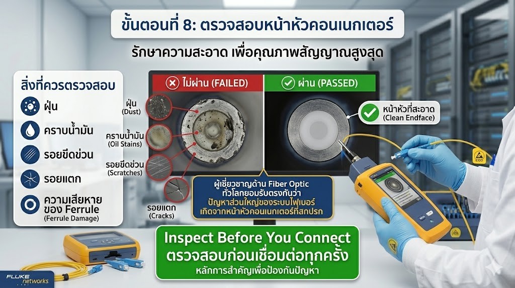
Step 8: Inspect the Connector End Face
Before putting the connection into service, inspect the connector end face using a Fiber Inspection Microscope.
Items that should be checked include:
- Dust particles
- Oil contamination
- Scratches
- Cracks
- Ferrule damage
Fiber Optic professionals worldwide agree that the majority of fiber system problems are caused by contaminated connector end faces.
Therefore, the principle of Inspect Before You Connect should always be followed before connecting the fiber to the system.
Step 9: Verify the Connection Using a Visual Fault Locator (VFL)
After the connector installation is completed, perform a preliminary inspection using a VFL.
The VFL injects a red laser light into the glass fiber. If red light is observed leaking along the cable path, it may indicate:
- A broken fiber
- A cracked fiber
- A bent fiber
- An abnormal connection point
This allows potential issues to be identified and corrected before the system is placed into operation.

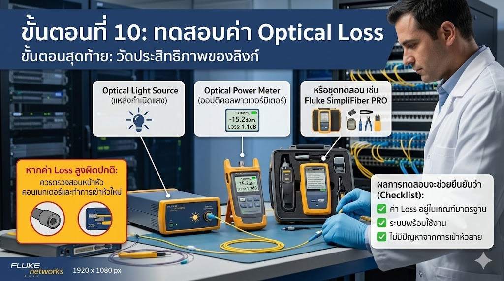
Step 10: Test Optical Loss
The final step is to measure the performance of the fiber link using:
- Optical Light Source
- Optical Power Meter
- Or test equipment such as the Fluke SimpliFiber PRO
The test results help verify that:
- The Loss value is within the acceptable standard range
- The system is ready for operation
- There are no issues caused by the cable termination process
If the Loss value is abnormally high, the connector end face should be inspected and the cable termination should be performed again if necessary.
Common Mistakes in Fiber Optic Cable Termination
Although fiber optic cable termination follows well-established standards, practical installation work still frequently encounters mistakes that affect system performance. In many cases, these issues may not appear immediately after installation but can lead to high Loss values, unstable signals, or reduced system lifespan over time.
Common mistakes include:
Stripping the Cable Too Deeply
Improper use of a Fiber Stripper may cause the blade to come into direct contact with the glass fiber Core, resulting in scratches or microscopic cracks on the fiber.
Although such damage may not be visible to the naked eye, it can increase Loss values and reduce the mechanical strength of the fiber.
Scratches on the Glass Fiber
During stripping, cleaning, or handling of the fiber, careless practices may create scratches on the surface of the glass fiber.
These imperfections can cause light scattering (Scattering), increasing signal attenuation within the system.
Poor Fiber Cleave Quality
Using a substandard Fiber Cleaver or operating a cleaver with a worn blade may result in an uneven fiber end face or an angled cut.
This reduces the quality of the connection or termination and can significantly increase Optical Loss.
Dirty Connector End Face
Dust particles, fingerprint oil residue, or even minor contamination on the connector end face can immediately obstruct the optical path.
Since the fiber Core is extremely small, connector end faces should always be inspected and cleaned before connection in accordance with the principle:
Inspect Before You Connect
Damaged Ferrule
The Ferrule is responsible for holding and aligning the glass fiber.
If the Ferrule becomes cracked, chipped, or worn, fiber alignment may be affected, reducing optical transmission efficiency and increasing Loss values.
Incomplete Fiber Insertion
During connector termination, if the glass fiber is not fully inserted to the specified position, a gap may form between the fiber end and the connector end face.
This can cause optical signal loss during transmission and negatively impact signal quality.
Incorrect Polarity Connection
This issue is particularly common in Duplex Fiber systems, where the Transmit (Tx) and Receive (Rx) channels must be connected correctly.
If the fibers are reversed, communication will fail even if the cable and connectors are otherwise in perfect condition.
Failure to Verify Loss After Installation
Many installations may appear complete, but without measuring Optical Loss after termination, there is no way to confirm whether the link meets the required performance standards.
Testing with an Optical Power Meter and Optical Light Source is therefore an essential step that should never be overlooked.
The Importance of Post-Termination Verification
Even minor mistakes during fiber optic cable termination can prevent the system from operating at full efficiency, result in Loss values that exceed standards, or create future connectivity issues.
Therefore, after installation is completed, technicians should always:
- Inspect connector end faces
- Verify Continuity
- Measure Optical Loss
- Confirm overall system performance
These verification steps ensure that the Fiber Optic system is fully operational, reliable, and compliant with professional installation standards.
Article Summary
Professional fiber optic cable termination requires more than simply assembling a connector. Every stage of the process is important, including cable preparation, cleaning, fiber cleaving, connector end-face inspection, and post-installation Loss testing.
When each step is performed correctly and according to industry standards, signal attenuation can be minimized, network stability can be improved, and the Fiber Optic system can deliver maximum performance and long-term reliability.