

Although Fiber Optic technology is highly efficient and widely used in modern communication systems, real-world installations often involve several critical risk points that can directly affect signal quality. Even a small installation mistake may result in high signal loss, unstable network performance, or complete system failure.
This article highlights 7 of the most common problems found in Fiber Optic installations, along with detailed solutions and preventive measures. These are real issues frequently encountered by network technicians in the field, with practical troubleshooting methods that are easy to inspect, apply, and prevent from the very beginning.
Why Is Fiber Optic Installation More Complex Than It Seems?
Fiber optic cables transmit data using light. While the concept may sound simple, in real-world applications, light signals are far more sensitive to interference than traditional electrical signals. Dust particles, excessive cable bending, improper splicing, or even tiny scratches on a connector surface can dramatically increase signal loss and potentially cause network failure.
Based on real field experience, network technicians have found that more than 80% of recurring Fiber Optic problems are caused by preventable installation mistakes. Most of these issues follow clear patterns and can be solved with the right procedures and tools.
This article compiles 7 of the most common Fiber Optic installation problems, along with practical solutions and preventive techniques that can be effectively applied in the field.
Explanation
- 80% of Fiber Optic Installation Problems Can Be Prevented
- 0.3 dB: The Commonly Accepted Maximum Splice Loss per Connection
- 30 mm: The Minimum Bend Radius for Single-Mode Fiber
7 Common Problems in Fiber Optic Installation and How to Fix Them
1. Weak Signal (High Optical Loss) — The Most Common Problem in Fiber Optic Installation
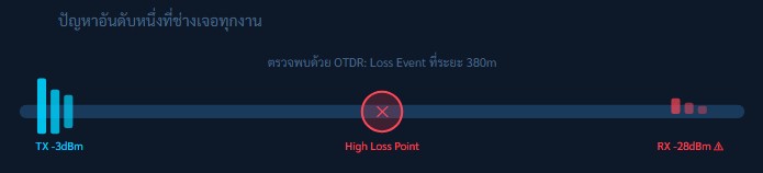
Excessive Optical Loss is one of the most fundamental yet difficult problems to diagnose in Fiber Optic systems. In many cases, the cable may appear physically normal from the outside, but the signal arriving at the destination is too weak for devices to communicate properly.
For Single-mode Fiber, the standard attenuation value is typically around 0.35 dB/km. If the measured loss exceeds this value, the root cause should be identified immediately to prevent network instability or system failure.
Main Causes
- Loose or improperly locked connectors
- Dust, dirt, or oil contamination on Fiber connectors
- Multiple splice points with accumulated loss
- Internal cracks or damage within the cable
- Transmission distance exceeding the Link Budget
Inspection Methods
- Use an OTDR to detect abnormal events along the cable
- Measure Total Loss using an Optical Power Meter (OPM)
- Inspect connectors with a Fiber Scope
- Test each network segment individually to isolate the faulty point
Solutions
- Clean every connector properly using an IEC 61300-3-35 compliant Fiber Cleaner
- Inspect all splice points using an OTDR and re-splice any point with a loss exceeding 0.3 dB
- Replace connectors that show cracks, scratches, or rough surface conditions
- Install an Optical Amplifier if the transmission distance exceeds the designed Link Budget
- Verify that the Patch Cord matches the correct connector type (SC / LC / FC / ST)
Using the OTDR Bidirectional Testing method by measuring from both directions and calculating the average value provides more accurate loss measurements than testing from only one direction. This technique also helps identify which side of the fiber link is closer to the problem point, making troubleshooting faster and more precise.
2. Excessive Bend Radius — The Hidden Fiber Killer
Excessive Bend Radius — Bending Beyond the Recommended Limit
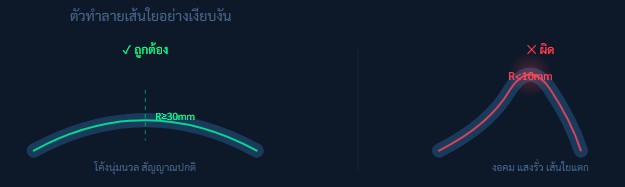
The glass fibers inside a Fiber Optic cable are flexible, but they are not designed to withstand excessive bending. When a cable is forced to bend beyond its Minimum Bend Radius, the light traveling through the fiber core can escape from the core itself, causing a sudden increase in signal loss. In severe cases, the glass fiber may crack or break permanently, resulting in irreversible damage to the cable.
Standard Bend Radius Values
- Single-mode Fiber (SMF): ≥ 30 mm (Static)
- Single-mode Fiber (SMF): ≥ 60 mm (Dynamic)
- Multimode Fiber (MMF): ≥ 30 mm (Static)
- Micro-bending sensitive condition: < 10 mm = Potential Damage
Common Risk Situations
- Pulling cables through sharply curved conduits
- Overtightening cables with Cable Ties
- Folding cables sharply inside Rack cabinets
- Cables being compressed under carpets or doors
Prevention and Solutions
- Use Fiber Raceway or Conduits with built-in Bend Radius Guides
- Use Low-profile Cable Ties and avoid excessive tightening
- Use Bend-Insensitive Fiber (BIF / G.657A) in areas where tight bends are unavoidable
- Create Slack Loops of at least 30 cm every 5–10 meters in confined spaces
- Avoid sharp 90° cable turns and use gradual 45° curves instead
If the OTDR shows a Gradual Loss over a section of the cable rather than a single event point, while the cable appears physically normal from the outside, the Bend Radius along that path should be inspected carefully. Accumulated Micro-bending can cause abnormal OTDR slope patterns and gradual signal degradation.
3. Poor Fusion Splice — The Connection Point That Disrupts Signal Transmission
Poor Fusion Splice — Improper Fiber Splicing That Causes Signal Loss
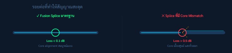
Fusion Splicing is the process of permanently joining two Fiber Optic cable ends together using an electric arc. This procedure requires micrometer-level precision. If the cores of both fibers are not perfectly aligned, the light signal cannot transfer efficiently from one fiber to the other, resulting in high signal loss.
In the case of Mechanical Splicing, which does not use heat fusion, these alignment issues and signal loss problems are even more common.
Causes of Poor Fusion Splicing
- Incorrect fiber cutting angle (Cleave Angle > 0.5°)
- Dirty fiber surfaces before splicing
- Fusion Splicer not properly calibrated
- Arc power settings unsuitable for the fiber type
- Using Mechanical Splice instead of Fusion Splice for long-term applications
IEC / TIA Standard Values
- Fusion Splice: ≤ 0.1 dB (Typical Standard)
- Fusion Splice: ≤ 0.3 dB (Maximum Acceptable)
- Mechanical Splice: ≤ 0.5 dB
- Cleave Angle Standard: ≤ 0.5°
Prevention and Solutions
- Use a high-quality Fiber Cleaver capable of achieving a Cleave Angle ≤ 0.5°, and inspect the fiber end face with a magnification tool
- Clean fiber surfaces with 99% IPA (Isopropyl Alcohol) and a Lint-free wipe before every splice
- Calibrate the Fusion Splicer regularly according to manufacturer recommendations (every 3–6 months)
- Check the Estimated Loss value displayed on the Fusion Splicer after every splice. If the value exceeds 0.3 dB, the splice should be redone immediately.
- Always apply a Splice Protection Sleeve and complete the Heat-shrink process properly to protect the splice point from physical damage and environmental factors.
It is important to understand that the Estimated Loss displayed on a Fusion Splicer is only an estimation based on Core Offset alignment and does not represent the actual measured loss. Therefore, every splice should be verified with an OTDR test after completion to ensure accurate performance and reliable signal quality.
4. Dirty Fiber End-Face — The Invisible Enemy of Fiber Optic Networks
Dirty Fiber End-Face — Contaminated Fiber Connector Surfaces

A dust particle as small as 1 micrometer is enough to block or significantly disrupt light transmission in a Single-mode Fiber, which has a core size of only 9 micrometers. Oils from human fingers, moisture in the air, and dust inside rack environments are all common sources of contamination.
Although this issue is very easy to prevent and fix, it is also one of the most frequently overlooked problems in Fiber Optic installations.
Common Causes
- Connector dust caps removed and not replaced
- Touching connector end-faces with bare hands
- Not cleaning the connector before every connection
- High-dust rack environment without air filtration
- Using regular cloth instead of lint-free wipes
Inspection Tool
- Fiber Inspection Scope (200–400x magnification)
- Portable Video Fiber Scope for field inspection
- IEC 61300-3-35 standard compliance for Pass/Fail evaluation
- AI-based inspection apps on smartphones for automated fiber end-face analysis
Standard Cleaning Procedure
- Dry Clean First: Use a one-click ferrule cleaner before every connection
- Wet + Dry Method: If contamination remains, clean using 99% IPA with a lint-free wipe, followed by a dry wipe
- Inspect: Always inspect the connector with a Fiber Scope before plugging it in
- Never blow: Never blow with your mouth—moisture and saliva are more harmful than dust particles
- Always install dust caps whenever the connector is not in use
A simple but essential rule in Fiber Optic work is: “Inspect Before You Connect.”
This must be followed every time without exception, even for brand-new connectors straight from the box, as airborne dust during transport or storage can still cause contamination and performance loss.
5. Physical Damage — Preventable Cable Stress and Deformation
Physical Damage — Cable Crushing and Excessive Twisting Issues

Although modern Fiber Optic cables are designed with multiple protective layers, a single point of pressure is enough to cause internal glass fiber breakage. This is especially common in construction sites where cables are installed first and later covered, or in rack environments where multiple cables are stacked and compressed together.
Common Risk Situations
- Doors pinching cables passing under thresholds
- Heavy objects placed on top of cables
- Overfilled conduits (Fill Ratio > 40%)
- Outdoor cables being run over by vehicles without proper protection
- Over-tightened cable ties compressing the cable jacket
Fault Detection Methods
- OTDR will show reflection peaks or distinct loss events
- Fault location can be identified accurately within approximately 1 meter
- Visual inspection along the entire cable route
- Use of Visual Fault Locator (VFL) red laser to trace breaks
Repair and Prevention
- Locate the fault position using OTDR and access the damaged section by opening the pathway
- Cut out the damaged segment and perform a new splice (direct repair of the fiber itself is not possible)
- Use Armored Fiber Cable in high-risk areas where physical pressure is expected
- Install Fiber Optic cables inside HDPE ducts or steel conduits in high-risk areas to provide strong mechanical protection against crushing, bending, and external impact.
- Place clear warning labels such as “Fiber Optic Cable Below” along the entire cable route to prevent accidental damage during future construction or maintenance work.
A Visual Fault Locator (VFL) can be used by injecting a red laser light into the fiber optic cable. If there is a break, crack, or severe bend in the cable, the light will leak out at that point and become visible to the naked eye. This makes VFL a highly effective tool for basic troubleshooting and fault detection before performing more detailed analysis with an OTDR.
6. Wrong Fiber Type Selection — The Most Difficult Installation Mistake to Fix
Wrong Fiber Type Selection — Incorrect Cable Choice That Affects the Entire Network
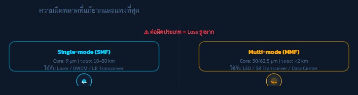
Single-mode and Multi-mode Fiber have core sizes that differ by approximately 5–7 times. If an SMF transceiver is used with an MMF cable (or vice versa), it can cause severe Modal Dispersion and significant Core Mismatch Loss. In some cases, the loss can reach as high as 20–30 dB, which is enough to make the entire system completely inoperable.
Common Mistakes
- Connecting SMF transceivers to MMF cables (or vice versa)
- Mixing OM3 and OM4 fibers within the same link
- Using OS1 (indoor-rated) cable for outdoor installations
- Selecting OM1 fiber for 10G transmission beyond 33 meters
- Using incorrect patch cords in Fiber Distribution Frames (FDF)
Fiber Type Selection Table
- OM1 (62.5 µm): 1G / distance ≤ 275 m
- OM3 (50 µm): 10G / distance ≤ 300 m
- OM4 (50 µm): 40G / 100G / distance ≤ 150 m
- OS2 (9 µm Single-mode): Long distance 10–80 km
Prevention Methods
- Design the system and select fiber types before procurement, ensuring compatibility with the chosen transceivers
- Use color-coded labels on patch cords (Yellow = SMF, Orange = MMF OM2, Aqua/Blue = OM3/OM4)
- Always check transceiver datasheets to confirm whether they support SMF or MMF and the operating wavelength
- In emergency cases where SMF and MMF must be connected, use a Mode Conditioning Patch Cord
Quick Identification Tip
To distinguish SMF and MMF using a simple method, inject light using a VFL and observe the output:
- SMF: produces a small, sharp point of light
- MMF: shows a wider, more diffused light pattern
However, the most reliable method is always to verify the cable jacket color code and manufacturer datasheet.
7. Exceeding Link Budget — Miscalculation That Breaks the Entire System
Exceeding Link Budget — When Transmission Distance Exceeds Equipment Capability
Link Budget refers to the maximum optical power that a Fiber Optic system can “consume” along the entire transmission path. It is calculated from TX Power minus Receiver Sensitivity. If the total accumulated loss (including fiber, splices, connectors, and safety margins) exceeds the budget, the system may become unstable or fail completely.
Link Budget Formula
- Budget (dB) = TX Power − Receiver Sensitivity
- Cable Loss = Distance (km) × 0.35 dB/km
- Splice Loss = Number of splices × 0.15 dB
- Connector Loss = Number of connector pairs × 0.75 dB
- Safety Margin = Always add 3 dB minimum
Common Calculation Mistakes
- Forgetting to include connector loss in Fiber Distribution Frames (FDF)
- Not accounting for aging loss over long-term usage (e.g., 10 years)
- Ignoring splitter loss in PON/FTTH systems
- Using incorrect transceiver datasheet values or wrong model assumptions
- Not considering slack loops and storage-related losses
Prevention Methods
- Always calculate Link Budget using a spreadsheet before purchasing equipment
- Include at least a 3 dB safety margin (6 dB for critical systems)
- Use an Optical Power Meter (OPM) to verify actual loss after installation and compare with calculated values
- Update the Link Budget whenever new components such as splitters, connectors, or splices are added
- For PON/FTTH systems, calculate splitter loss separately (e.g., 1:32 split ≈ 15 dB loss)
Tools such as EXFO FTB series, vendor software toolboxes, or pre-built Google Sheets templates can help automate Link Budget calculations and significantly reduce human error.
Essential Field Toolkit for Fiber Optic Technicians
Having the right tools in the field is critical for Fiber Optic work. Proper equipment can reduce troubleshooting time from hours to just minutes, improve accuracy, and prevent unnecessary rework during installation and maintenance.
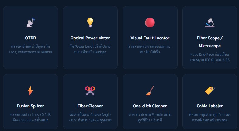
OTDR (Optical Time-Domain Reflectometer)
Used to locate fault positions along the fiber link and measure loss and reflectance throughout the entire cable. It helps identify events such as breaks, splices, and excessive attenuation.
Optical Power Meter (OPM)
Measures the actual optical power at the end of the fiber. The result is compared with the calculated Link Budget to verify system performance and signal integrity.
Visual Fault Locator (VFL)
Injects a visible red laser into the fiber to quickly detect breaks, bends, or contamination. Fault points can be identified visually along the cable route.
Fiber Scope / Microscope
Inspects the fiber end-face before connection to ensure cleanliness and quality. It follows the IEC 61300-3-35 standard for Pass/Fail inspection criteria.
Fusion Splicer
Used to permanently join two fiber ends by fusion. It achieves very low splice loss (< 0.1 dB) when properly calibrated and maintained regularly.
Fiber Cleaver
Precisely cuts fiber ends to ensure a clean break with a cleave angle of less than 0.5°, which is essential for high-quality splicing results.
One-Click Cleaner
Provides fast and effective dry cleaning of fiber ferrules in seconds, ensuring connector surfaces are free from dust and contamination before connection.
Cable Labeler
Used to label all fiber cables and ports clearly, reducing human error during installation, maintenance, and future troubleshooting.
FAQ — Field Technician Questions
What loss value is considered “pass” according to standards?
It depends on the standard being used. In general, TIA-568 specifies:
- Connector loss ≤ 0.75 dB per pair
- Splice loss ≤ 0.3 dB per point
- Cable loss ≤ 0.35 dB/km for Single-mode Fiber (OS2)
However, the total channel loss must always be within the Link Budget of the transceiver being used, with a safety margin of at least 3 dB.
What is the difference between OTDR and Optical Power Meter? Which one should be used?
OTDR sends light pulses into the fiber and analyzes the reflected signal, creating a “map” of the entire link. It can pinpoint the exact location of faults, making it ideal for troubleshooting and acceptance testing.
An Optical Power Meter (OPM), on the other hand, measures only the total received power at the end of the link. It can confirm overall loss but cannot identify fault locations.
In real field applications, both tools should be used together for accurate diagnosis.
Why does fiber loss increase after rain?
Common causes include:
- Water ingress into poorly sealed connectors or splice closures
- Water accumulation in conduits causing physical pressure on cables
- Thermal expansion of cable jackets leading to increased micro-bending
Prevention includes verifying IP ratings of splice closures and connector housings to ensure suitability for environmental conditions.
What is the difference between Mechanical Splice and Fusion Splice? Which should be used?
Fusion Splicing permanently joins two fiber ends using heat fusion, resulting in very low loss (≤ 0.1 dB) and high durability. However, it requires an expensive fusion splicer.
Mechanical Splicing uses an index-matching gel to align fibers without heat. It is cheaper and faster but has higher loss (≤ 0.5 dB) and may degrade over time.
For permanent installations, Fusion Splicing is always recommended. Mechanical Splicing should only be used for temporary or emergency repairs.
How long does Fiber Optic cable last?
High-quality fiber cables have a theoretical lifespan of 25–30 years. In practice, lifespan depends heavily on environmental conditions. Outdoor cables exposed to UV, humidity, and temperature changes tend to degrade faster than indoor installations.
The first components to degrade are typically the connector ferrules and outdoor cable jackets exposed to UV radiation.
Summary
High-quality Fiber Optic installation is not simply about achieving “working signal,” but ensuring that the network is stable and reliable for long-term use. Therefore, using a pre-commissioning checklist is a critical step to reduce future problems such as signal loss, connection errors, and cable damage.
The process should begin with proper Link Budget calculation, selecting appropriate fiber types and equipment, and carefully checking cable bend radius. Connector end-faces must be cleaned before every use, and splice loss as well as end-to-end loss should be verified using standard tools such as OTDR and Optical Power Meter (OPM) to ensure full system performance.
In addition, proper labeling and storing OTDR test reports make future maintenance and troubleshooting much easier. These practices represent professional Fiber Optic installation standards that improve system reliability while reducing long-term maintenance costs.
.
If you need to rent network testing equipment or require installation services, feel free to inquire for more information at Metro Technology Co., Ltd. or click here to contact us.